If you've ever stood at the timber yard or sat in your ute trying to make sense of Australian timber span tables, you know the headache of getting stuck on the very first column: Floor Load Width (FLW). It sounds like engineer jargon, but on site, getting this number wrong either costs you thousands in oversized timber you didn't need, or leaves you with a bouncing subfloor that a building certifier will fail in two seconds.
Whether you're framing up an outdoor deck, a ground-floor home extension, or sizing subfloor floor joists and bearers under AS 1684.2:2021 (Residential Timber-Framed Construction), this guide breaks down the exact formulas, span tables, and rules chippies need on site.
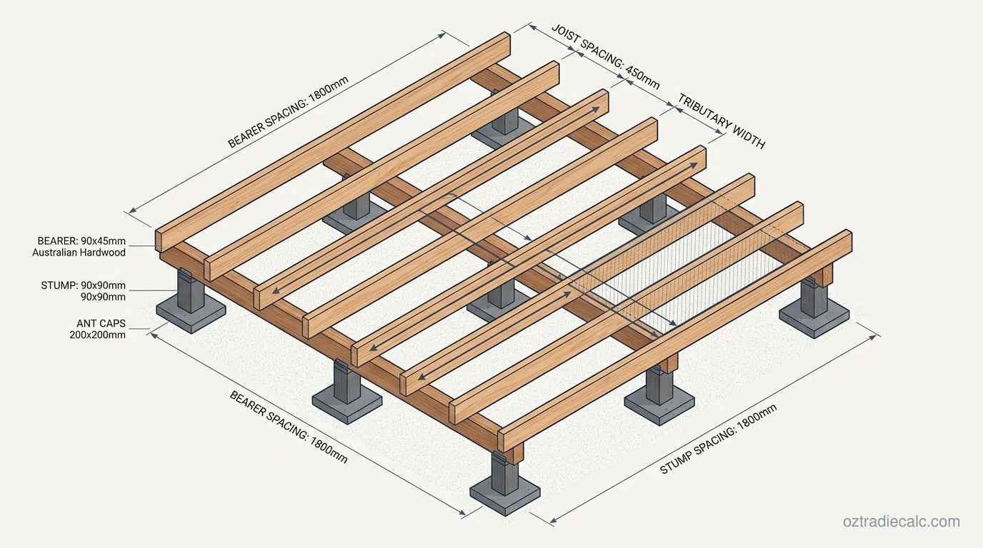
1. Quick FLW & Bearer Sizing Summary Table
Need the quick answer on site? Here is the cheat-sheet summary of Australian Standard AS 1684.2 Floor Load Width formulas and typical timber member sizes:
| Bearer Position / Setup | AS 1684 FLW Formula | Continuous Joist Factor | Typical Bearer Sizing (MGP10 / LVL) |
|---|---|---|---|
| External / Perimeter Bearer | FLW = Joist Span ÷ 2 | 1.0× | 2/90 × 45 mm (up to 1.8m stump span) |
| Internal Centre Bearer (Single Spans) | FLW = (Span 1 ÷ 2) + (Span 2 ÷ 2) | 1.0× | 2/140 × 45 mm (up to 2.1m stump span) |
| Internal Centre Bearer (Continuous Joists) | FLW = 1.25 × (Span 1 ÷ 2 + Span 2 ÷ 2) | 1.25× factor | 2/190 × 45 mm or 130 × 45 LVL |
| External Bearer with Cantilever | FLW = (Joist Span ÷ 2) + Cantilever Length | 100% of Overhang | 2/140 × 45 mm (max 25% backspan cantilever) |
2. What is Floor Load Width (FLW) in AS 1684?
When sizing subfloor timber members from Australian Standard span tables, the most critical dimension you need before opening the tables is the Floor Load Width (FLW). Many first-year apprentices and owner-builders make the mistake of measuring the total room length or width and trying to find that number in the span tables. But structural bearers do not carry the entire room at once.
In plain terms, Floor Load Width (FLW) is the tributary width of flooring (measured in metres) whose total downward weight—both the dead load of the structure and the live load of people and furniture—is transferred directly onto a single bearer line.
Because floor joists are supported at both ends, the gravitational load across any joist bay is shared equally between the two supports. This means a bearer only supports half the joist span on its left and half the joist span on its right.
Under AS/NZS 1170.1 (Structural Design Actions), Australian domestic floors are engineered to support:
- Dead Load (G): The self-weight of the framing timber, 19mm particleboard flooring (Yellow Tongue) or hardwood decking boards, and floor finishes (typically 0.4 kPa).
- Live Load (Q): A uniformly distributed load of 1.5 kPa (or a 1.8 kN concentrated point load) for general residential living areas.
Sizing your timber bearers accurately against these loads prevents springy, bouncing floors, protects plasterboard joints from cracking upstairs, and ensures your subfloor passes first-round building certifier inspections. If you want to estimate your complete subfloor timber take-off, check our free Bearer and Joist Calculator.
3. The Core FLW Formulas (External, Internal & Cantilevers)
Calculating FLW is straightforward once you identify the position of the bearer relative to the floor joists spanning over it. There are three standard framing configurations on Australian sites:
A. External / Perimeter Bearers (Single-Side Load)
An external bearer runs along the outside edge of the subfloor (or ledger board line). Because joists only sit on one side of this bearer (with the other end resting on an internal bearer), this member only carries half of that single joist span.
Example: If your floor joists span 3.0 metres between the perimeter wall and the centre bearer, the external bearer carries an FLW of 3.0m ÷ 2 = 1.5m.
B. Internal / Intermediate Bearers (Double-Side Load)
An internal bearer sits between two joist bays. It carries the tributary load coming from both adjacent bays simultaneously.
If the joist span is identical on both sides (for example, continuous joists spanning 2.4m on each bay), the equation simplifies to:
Example: If joists span 2.4m from the left external bearer to the centre bearer, and 2.4m from the centre bearer to the right external bearer, the internal centre bearer carries (2.4 ÷ 2) + (2.4 ÷ 2) = 1.2m + 1.2m = 2.4m FLW.
C. Bearers Supporting Cantilevered Joists (Decks & Balconies)
When floor or deck joists extend past the outer bearer line to create an overhang or cantilever, that overhang is not shared with any other support. The entire cantilever load hangs on the outer bearer.
Important AS 1684 rule: Under AS 1684.2 Clause 4.3.2, joist cantilevers must not exceed 25% of the actual backspan unless specifically engineered. For outdoor framing guidelines and board calculations, refer to our Decking Calculator.
4. Step-by-Step Practical Site Example
To see how this works on a real Australian residential framing job, consider a standard 7.2m long × 4.2m wide ground-floor deck or home extension:
- Total Subfloor Dimensions: 7.2m length along bearer runs, 4.2m width across joist spans.
- Bearer Layout: 3 lines of bearers spanning 7.2m (2 External Bearers + 1 Centre Internal Bearer).
- Stump / Pier Spacing: Brick piers or treated pine posts spaced at 1.8m centres along each bearer line.
- Joist Span: 90x45 MGP10 joists at 450mm centres, spanning 2.1m over each bay, with a 300mm cantilever past External Bearer C.
Step 1: Calculate External Bearer A (House Ledger Side)
Bearer A supports the inside edge of Bay 1 joists (2.1m clear span) with no cantilever.
FLW = 2.1m ÷ 2 = 1.05m
Step 2: Calculate Centre Internal Bearer B
Bearer B sits in the middle and supports half of Bay 1 (2.1m) plus half of Bay 2 (2.1m).
FLW = (2.1m ÷ 2) + (2.1m ÷ 2) = 1.05m + 1.05m = 2.10m
Step 3: Calculate External Bearer C (Cantilever Edge)
Bearer C supports half of Bay 2 (2.1m) plus the full 300mm (0.3m) joist cantilever overhang.
FLW = (2.1m ÷ 2) + 0.30m = 1.05m + 0.30m = 1.35m
Notice the clear difference in structural demand: the centre bearer carries 2.10m FLW (twice the load of the perimeter bearer), meaning it requires either a deeper timber section, double-laminated members, or closer stump spacing.
5. AS 1684.2 Bearer & Joist Span Tables (MGP10 & LVL)
Once you know your Floor Load Width and stump spacing (post span), you can open AS 1684.2 Supplement 4 (Seasoned Softwood MGP10) or Supplement 2 (F7 Hardwood), navigate to Table 1: Floor Bearers — Supporting Floor Loads Only, and select your member size.
Span tables group FLWs into standardized brackets: 1.2m, 2.4m, 3.6m, and 4.8m. Always round your calculated FLW up to the next table column. For example, if your calculated FLW is 1.35m, you look under the 2.4m FLW column.
A. AS 1684 Floor Bearer Span Table (MGP10 vs LVL)
| Calculated FLW (m) | Stump Span (Post Spacing) | Single Span Bearer (MGP10) | Continuous Span Bearer (MGP10) | Engineered LVL (E14) |
|---|---|---|---|---|
| Up to 1.2 m | 1.8 m | 2/90 × 45 mm | 2/90 × 45 mm | 90 × 45 mm LVL |
| Up to 1.2 m | 2.4 m | 2/140 × 45 mm | 2/120 × 45 mm | 130 × 45 mm LVL |
| Up to 2.4 m | 1.8 m | 2/120 × 45 mm | 2/90 × 45 mm | 100 × 45 mm LVL |
| Up to 2.4 m | 2.1 m | 2/140 × 45 mm | 2/120 × 45 mm | 130 × 45 mm LVL |
| Up to 2.4 m | 2.7 m | 2/190 × 45 mm | 2/170 × 45 mm | 170 × 45 mm LVL |
| Up to 3.6 m | 2.1 m | 2/190 × 45 mm | 2/140 × 45 mm | 150 × 45 mm LVL |
| Up to 3.6 m | 2.4 m | 2/240 × 45 mm | 2/190 × 45 mm | 200 × 45 mm LVL |
B. AS 1684 Floor Joist Maximum Allowable Spans (MGP10 @ 1.5 kPa Floor Load)
| Joist Size (D × B mm) | Single Span @ 450mm Centres | Continuous Span @ 450mm Centres | Single Span @ 600mm Centres | Continuous Span @ 600mm Centres |
|---|---|---|---|---|
| 90 × 45 mm | 1.5 m | 1.8 m | 1.3 m | 1.6 m |
| 120 × 45 mm | 2.0 m | 2.4 m | 1.8 m | 2.1 m |
| 140 × 45 mm | 2.4 m | 2.8 m | 2.1 m | 2.5 m |
| 190 × 45 mm | 3.2 m | 3.8 m | 2.8 m | 3.3 m |
| 240 × 45 mm | 4.1 m | 4.8 m | 3.6 m | 4.2 m |
| 290 × 45 mm | 4.9 m | 5.7 m | 4.3 m | 5.0 m |
Notice how Continuous Span bearers and joists (members running unbroken over three or more supports) achieve 15%–25% greater spans than Single Span members of the same cross-section. This is because continuous timber experiences opposing bending moments over internal supports, significantly reducing mid-span deflection.
To cross-check joist member thicknesses, stud spacing, and rafter spans, use our comprehensive Timber Span Calculator.
6. Common Site Mistakes & Inspection Traps
Subfloor framing defects are among the most frequent issues flagged on private certifier inspection reports in New South Wales, Victoria, and Queensland. Watch out for these four common site traps:
1. Confusing Joist Spacing with Joist Span
Joist spacing (typically 450mm or 600mm centres) determines the flooring board thickness and joist section size. It has zero effect on Bearer FLW. Floor Load Width is determined entirely by the clear distance between bearer support lines (the joist span).
2. Missing Roof Load Width (RLW) on Load-Bearing Walls
If a bearer supports an external load-bearing wall or an internal wall carrying roof trusses, you cannot use Table 1 (Floor load only). You must use AS 1684.2 Table 4 (Bearers supporting load-bearing walls), which requires calculating both FLW and Roof Load Width (RLW) based on your roof pitch and truss spans.
3. Improper Lamination of Double Bearers (2/140x45)
Under AS 1684.2 Clause 2.3, built-up double bearers must be properly fixed together to act as a single composite structural member. Fasten pairs with two rows of 3.06mm diameter framing nails at maximum 300mm centres along the member length, or M10 galvanized coach bolts at maximum 600mm centres.
4. Missing Termite Barriers & Damp-Proof Course (DPC)
Under NCC 2022 Part 3.1, timber framing in contact with masonry or concrete stumps must have an approved Damp-Proof Course (DPC) strip to stop rising moisture, plus continuous ant caps or accredited visual termite inspection zones (minimum 75mm clear inspection gap to ground line). If you are framing subfloors near perimeter earthworks, check our Retaining Wall Calculator for drainage and soil setback compliance.