On modern Australian builds packed with R5.0 ceiling insulation, induction cooktops, and 7kW EV chargers, old site habits like "just chuck 2.5mm² on a 20A breaker" are getting Certificate of Electrical Safety (COES) audits failed every week. If you only look at nominal amps on paper, you miss the 50% thermal derating penalty in roof batts or the strict 5% voltage drop cliff on long runs.
Under AS/NZS 3000:2018 (Wiring Rules) and AS/NZS 3008.1.1:2025, compliant cable selection requires the Three-Check Method: verifying derated current capacity (Ib ≤ In ≤ Iz), calculating voltage drop limits, and confirming earth fault loop impedance for automatic 0.4s trip times. Here is the practical on-site cheat-sheet, standard tables, and worked sizing examples for Aussie sparkies.
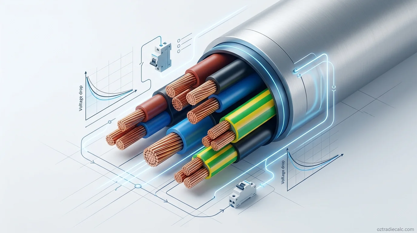
1. Quick Circuit Sizing & Breaker Reference Table
Need an immediate on-site answer for standard domestic and light commercial installations? The table below outlines standard Australian copper TPS (Thermoplastic-Sheathed) cable sizes, matched circuit breakers, and typical maximum run lengths before voltage drop requires upsizing:
| Circuit Type | Standard Cable Size | Matching Circuit Breaker (MCB/RCBO) | Max Continuous Load | Max Safe Route Length (5% Vd) | Typical Cable Type |
|---|---|---|---|---|---|
| LED Lighting Circuit | 1.5 mm² Twin & Earth | 10A Type C | 8A – 10A | ~ 38 metres | Flat TPS (Copper V-90) |
| General Power Outlets (GPO) | 2.5 mm² Twin & Earth | 16A or 20A Type C | 16A – 20A | ~ 24 – 30 metres | Flat TPS (Copper V-90) |
| Dedicated Air Conditioner (3.5kW–5kW) | 2.5 mm² – 4.0 mm² Twin & Earth | 20A Type C or D | 14A – 18A | ~ 28 metres (2.5mm²) / 45m (4mm²) | Flat TPS / Orange Circular |
| Induction Cooktop / Freestanding Oven | 6.0 mm² Twin & Earth | 32A Type C | 28A – 32A | ~ 34 metres | Flat TPS (Copper V-90) |
| EV Home Charger (7.2kW Single Phase) | 6.0 mm² – 10.0 mm² | 32A or 40A Type C/B | 32A Continuous | ~ 26 metres (6mm²) / 42m (10mm²) | XLPE / Heavy Duty TPS |
| Single Phase Sub-Board (Garage / Studio) | 10.0 mm² – 16.0 mm² | 40A or 50A Type C | 40A – 50A | ~ 35 – 55 metres | Orange Circular / XLPE |
| Three-Phase Sub-Mains (Shed / Workshop) | 16.0 mm² – 25.0 mm² 4C + E | 63A Type C | 50A – 63A per phase | ~ 45 – 70 metres | Orange Circular XLPE (0.6/1kV) |
Note: These lengths assume unbunched cables installed with standard ceiling thermal conditions. If your cable is buried in thick insulation or grouped with other circuits, you must apply derating factors. To calculate exact customized runs in seconds, use our free AS 3008 Cable Sizing Calculator.
2. The Three-Check Method (AS/NZS 3008 Framework)
Under Australian Standard AS/NZS 3008.1.1, every electrical cable must satisfy three independent technical criteria. The final compliant cable size is always the largest cross-sectional area dictated by any one of the three checks:
Check 1: Current-Carrying Capacity (Ampacity)
The cable must carry the full continuous load current without its insulation exceeding its rated operating temperature (75°C for standard V-90 PVC, or 90°C for XLPE/cross-linked polyethylene).
Fundamental Coordination Rule: Ib ≤ In ≤ Iz
- Ib (Design Current): The actual operating load of the connected equipment (or maximum demand calculated from AS 3000 Table C1).
- In (Protective Device Rating): The nominal rating of the circuit breaker or fuse (e.g. 20A MCB).
- Iz (Derated Cable Capacity): The actual real-world ampacity of the cable after applying all installation derating multipliers.
Check 2: Maximum Voltage Drop Limits
As current flows through cable conductors, internal resistance causes a voltage drop. If voltage drops too low at appliances, motors overheat, inverter systems disconnect, and electronics malfunction.
Under AS/NZS 3000 Clause 3.6.2, the total voltage drop from the point of supply (street mains or transformer) to the furthest outlet must not exceed 5% of the nominal voltage:
- 230V Single Phase: Maximum allowable drop = 11.5 Volts (Minimum voltage at load = 218.5V).
- 400V Three Phase: Maximum allowable drop = 20.0 Volts (Minimum voltage at load = 380.0V).
Tip: For consumer mains, the drop is customarily limited to 2% (4.6V), leaving 3% (6.9V) for final sub-circuits. Check your exact run with our Voltage Drop Calculator.
Check 3: Fault Loop Impedance & Short-Circuit Protection
If an active conductor shorts to earth (an earth fault), the total resistance of the supply transformer, active cable, and earth return path—called the Earth Fault Loop Impedance (Zs)—must be low enough to allow massive fault current to flow and instantly trip the protective device.
Under AS/NZS 3000 Table 8.1, the maximum disconnection time must not exceed:
- 0.4 seconds: For all final sub-circuits supplying socket-outlets (GPOs) up to 32A and hand-held equipment.
- 5.0 seconds: For distribution sub-mains and fixed stationary equipment.
Verify automatic trip times using our Fault Loop Impedance Calculator.
3. Real-World Derating Factors (Heat, Insulation & Grouping)
A cable's published "open-air" current rating is an engineered baseline (usually measured at 40°C ambient in free air). On Australian jobsites, cables are crammed into colorbond roof cavities, buried in pink ceiling batts, and bunched together inside conduits.
To find the true continuous rating ($I_z$), multiply the baseline table current ($I_t$) by the three key derating factors:
A. Ambient Temperature Correction Factor (Kt)
Australian roof cavities routinely hit 50°C to 60°C under corrugated iron during summer. If you size a 75°C PVC cable assuming mild 25°C weather, the cable will overheat and rapidly degrade.
- 40°C Ambient (AS 3008 Standard Baseline):
Kt = 1.00 - 45°C Ambient (Typical Summer Ceiling):
Kt = 0.93for PVC (75°C) /0.95for XLPE (90°C) - 50°C Ambient (Hot Metal Roof Cavity):
Kt = 0.87for PVC (75°C) /0.90for XLPE (90°C) - 55°C Ambient (Extreme Unventilated Space):
Kt = 0.79for PVC (75°C) /0.85for XLPE (90°C)
B. Thermal Insulation Derating Factor (Ki)
With Australian National Construction Code (NCC) energy efficiency requirements pushing ceiling insulation to R4.0–R6.0, cables trapped in thermal batts cannot dissipate heat:
| Installation Condition in Insulation | Insulation Length / Placement | Derating Multiplier (Ki) | Effective Cable Capacity Loss |
|---|---|---|---|
| Completely Surrounded in Bulk Insulation | ≥ 500 mm continuous length | Ki = 0.50 | 50% Capacity Reduction |
| Partially Surrounded (Touching Joist / Plasterboard) | One side in contact with timber/ceiling | Ki = 0.75 | 25% Capacity Reduction |
| Clipped to Joist Above Insulation | Air circulation above batts | Ki = 1.00 | No Derating Required |
Critical Sparky Rule: If a 2.5mm² TPS cable with a base rating of 24A is buried completely under ceiling batts ($K_i = 0.50$), its new safe capacity drops to 12.0 Amps. If you protect that circuit with a 20A circuit breaker, the installation is non-compliant and poses a structural fire hazard because $I_n (20A) > I_z (12A)$.
C. Grouping Correction Factor (Kg)
When multiple active circuits run side-by-side in a single conduit, cable tray, or ducting run, heat builds up between adjacent cables:
- 2 Circuits Touching:
Kg = 0.80 - 3 Circuits Touching:
Kg = 0.70 - 4 to 6 Circuits Touching:
Kg = 0.60 – 0.55 - Spaced by at least 1 Cable Diameter:
Kg = 1.00(No grouping penalty)
To check if your conduit sizing complies with maximum 40% occupancy space rules, use our Conduit Fill Calculator.
4. Voltage Drop Limits & Long Run Calculations
In large residential homes, rural properties, and commercial warehouses, cable length is almost always the deciding factor that forces you to upsize conductor gauge.
Under AS/NZS 3008.1.1 Section 4, voltage drop is calculated using the specific millivolt drop per ampere-metre ($V_c$) value for the chosen conductor size:
Standard AS/NZS 3008 Vc Reference Table (Copper Conductors @ 75°C)
| Conductor Cross-Section | Single Phase Vc Value (mV/A.m) | Three Phase Balanced Vc Value (mV/A.m) | Max Amps @ 25m (230V 5% Drop) |
|---|---|---|---|
| 1.5 mm² | 30.9 | 26.7 | 14.8 A |
| 2.5 mm² | 18.8 | 16.3 | 24.4 A |
| 4.0 mm² | 11.7 | 10.1 | 39.3 A |
| 6.0 mm² | 7.78 | 6.74 | 59.1 A |
| 10.0 mm² | 4.68 | 4.05 | 98.2 A |
| 16.0 mm² | 2.93 | 2.54 | 156.9 A |
| 25.0 mm² | 1.88 | 1.63 | 244.6 A |
5. Earth Conductor Sizing (AS/NZS 3000 Table 5.1)
In Australia's Multiple Earthed Neutral (MEN) wiring system, the protective earthing conductor carries lethal fault currents back to the switchboard neutral bar to trigger fast circuit breaker tripping.
Under AS/NZS 3000:2018 Table 5.1, the minimum cross-sectional area for copper protective earth conductors is determined by active conductor gauge:
| Active Conductor Size (Copper) | Minimum Copper Protective Earth Size | Standard Australian Twin & Earth Cable Spec |
|---|---|---|
| 1.5 mm² | 1.5 mm² | 1.5mm² Twin & Earth (1.5A + 1.5E) |
| 2.5 mm² | 2.5 mm² | 2.5mm² Twin & Earth (2.5A + 2.5E) |
| 4.0 mm² | 2.5 mm² | 4.0mm² Twin & Earth (4.0A + 2.5E) |
| 6.0 mm² | 2.5 mm² | 6.0mm² Twin & Earth (6.0A + 2.5E) |
| 10.0 mm² | 4.0 mm² | 10.0mm² Twin & Earth (10.0A + 4.0E) |
| 16.0 mm² | 6.0 mm² | 16.0mm² Twin & Earth (16.0A + 6.0E) |
| 25.0 mm² | 6.0 mm² | 25.0mm² Active with separate 6.0mm² Earth |
| 35.0 mm² | 10.0 mm² | 35.0mm² Active with separate 10.0mm² Earth |
| 50.0 mm² | 16.0 mm² | 50.0mm² Active with separate 16.0mm² Earth |
Sub-Board Earth Warning: When running sub-mains to outbuildings (such as a backyard shed or granny flat), the sub-mains protective earth must match Table 5.1, and if an independent earth stake is driven at the outbuilding, ensure the MEN link is installed correctly under AS 3000 Clause 5.5.3. Check earth resistance with our Earth Electrode Resistance Calculator.
6. Step-by-Step Practical Site Worked Examples
Scenario 1: 32A Single-Phase Induction Cooktop in Ceilings with Batts
A residential renovation in Brisbane requires wiring a new 7.4 kW (32A) induction cooktop. The cable run is 22 metres from the main switchboard, clipped to rafters but running through 2 metres of R5.0 ceiling insulation.
Step 1: Check 1 — Current Capacity & Derating
- Design Load (Ib): 32 Amps.
- Protective Device (In): 32A Type C RCBO.
- Installation Method: Partially surrounded in thermal batts (
Ki = 0.75), 45°C Queensland summer ceiling cavity (Kt = 0.93). Total derating multiplier =0.75 × 0.93 = 0.697. - Required Table Base Rating (It):
In ÷ 0.697 = 32A ÷ 0.697 = 45.9 Amps. - Under AS 3008.1.1 Table 10, a standard 6.0mm² copper TPS has a baseline rating of 46 Amps (Iz derated = 32.1A ≥ 32A In). 6.0mm² passes Check 1.
Step 2: Check 2 — Voltage Drop
- For 6.0mm² copper,
Vc = 7.78 mV/A.m. Vd = (22m × 32A × 7.78) ÷ 1000 = 5.47 Volts.- Percentage Drop =
(5.47V ÷ 230V) × 100 = 2.38%. - Since 2.38% is well under the 5% (11.5V) limit, 6.0mm² passes Check 2.
Step 3: Check 3 — Fault Loop & Final Selection
- 6.0mm² TPS comes with a 2.5mm² Earth conductor (fully compliant with AS 3000 Table 5.1).
- At 22m length, fault loop impedance is under 0.65Ω, guaranteeing instantaneous magnetic trip of the 32A Type C breaker well within 0.4 seconds.
- Final Decision: Install 6.0mm² Twin & Earth (6.0A + 2.5E) protected by a 32A Type C RCBO.
Scenario 2: 40A Three-Phase Sub-Mains to Backyard Workshop (45m Underground)
A customer in Melbourne wants a 40A three-phase sub-board in a detached shed. The cable route is 45 metres installed in underground heavy-duty (HD) PVC conduit at 600mm burial depth.
Step 1: Current Capacity Check
- Design Load: 40A per phase, protected by a 40A Type C 3-Pole MCB.
- Underground direct conduit in standard soil (25°C ground ambient): 10.0mm² 4C+E XLPE cable is rated at 58 Amps. 10.0mm² passes Check 1 easily.
Step 2: Voltage Drop Check (The Deciding Factor)
- For 10.0mm² three-phase balanced load,
Vc = 4.05 mV/A.m. Vd = (√3 × 45m × 40A × 4.05) ÷ 1000 = 12.62 Volts.- Percentage Drop =
(12.62V ÷ 400V) × 100 = 3.15%. - If the consumer mains drop is 1.5%, total installation drop =
1.5% + 3.15% = 4.65% ≤ 5.0%. 10.0mm² passes Check 2.
Step 3: Fault Loop & Earth Sizing
- Under Table 5.1, a 10.0mm² active conductor requires a minimum 4.0mm² Earth conductor.
- Final Decision: Install 10.0mm² 4-Core + 4.0mm² Earth Orange Circular (0.6/1kV) in HD PVC conduit protected by a 40A Type C MCB.
7. Top 5 AS 3000 Electrical Audit & Inspection Traps
During mandatory Certificate of Electrical Safety (COES) audits and council compliance checks, inspectors regularly issue non-compliance notices for these five cable sizing oversights:
- Ignoring 0.5× Thermal Insulation Derating: Running 2.5mm² TPS for power circuits buried deep under R5.0 batts on 20A breakers. If the cable is surrounded by insulation, you must either derate the breaker to 16A/10A or upsize the cable to 4.0mm².
- Exceeding 5% Total Voltage Drop on EV Chargers: Sizing a 32A electric vehicle charger with 6.0mm² cable on a long 35m+ route. Because EV charging runs at maximum load for 8 continuous hours, excessive voltage drop can cause the onboard charger to fault or overheat terminal lugs.
- Mismatched Earth Conductor on Sub-Mains: Using twin active cables with an undersized separate earth wire that fails AS 3000 Table 5.1 requirements (e.g. running 16mm² actives with a 2.5mm² earth instead of the mandatory 6.0mm² earth).
- Overfilling Conduits Past 40% Space Factor: Cramming 5 or 6 TPS cables into a standard 20mm or 25mm corrugated conduit, causing both severe grouping heat derating ($K_g = 0.55$) and physical insulation damage during pulling. Check maximum conduit limits with our Conduit Fill Calculator.
- Using Type B or D Breakers Inappropriately: Fitting Type D breakers on circuits with long cable runs without verifying fault loop impedance ($Z_s$). Because Type D breakers require 10–20× nominal current to trip magnetically, high fault loop resistance will fail the 0.4s automatic disconnection requirement under AS 3000 Table 8.1.